Basic Circuitry: Circuit Diagrams
Objectives and Overview
This lesson introduces circuit diagrams and provides an overview of how to use these visual representations of circuits in your electronics projects. Additionally, you’ll practice reading these diagrams and. By the end of the lesson, you should recognize the importance of circuit diagrams and be able to explain their role in electronics projects.
Lesson Objectives
- Understand how to read and use a circuit diagram.
- Recognize and explain the benefit of knowing how to read circuit diagrams.
- Be able to label and describe what is happening on a circuit diagram.
Circuit Diagrams
Circuit diagrams and schematics are visual representations of circuits. These images are used to convey information about how to wire a circuit. Often when looking for electronics projects the first step will be to wire up the circuit, and this will sometimes only include the diagram as a reference.
As you continue to explore Arduino projects (and Raspberry Pi projects in other courses) you’ll come across lots of styles of circuit diagrams. Occasionally you’ll see the terms circuit diagram and schematic used interchangeably, but the diagrams that you’ll be using in this course more closely resemble the Arduino and breadboard. Other schematics are more complex and difficult to use until you begin to understand how the components and circuits are represented.
It’s beneficial to understand how to read both types of diagrams and schematics, but in this course you’ll be working with the diagrams that contain clear visuals of the Arduino, breadboard, components, and wires. Once you develop a foundation for how circuit diagrams relate to the Arduino, breadboard, and components you’ll be able to level up your knowledge and understand schematics (if you’re interested).
Fritzing Diagrams
The majority of diagrams that you’ll encounter for Arduino projects are known as Fritzing diagrams. Fritzing is an open source project that is used to create both traditional schematics as well as the more readable ones that you’ll be using.
Let’s take a look at one of the diagrams. This is a basic breadboard LED circuit with a resistor:

One of the best tips for working with these diagrams is to orient your Arduino and breadboard so that it sits in the same position as in the diagram.
If you set your Arduino and breadboard up like in this diagram, you can then clearly see the Arduino pins that the jumper wires connect to. Most diagrams tend to use red for any connection related to Power (5V) and black for wires related to ground (GND). This won’t always be the case, but it’s used fairly often.
You’ll see that jumper wire images are used to connect the Arduino to the breadboard/components. In this example, the red jumper is connected to the + (power) rail of the breadboard and the black jumper is connected to the – (ground) rail of the breadboard.
The other things that are shown are the LED and the resistor. From examining this diagram, the yellow jumper connects the positive leg of the LED to pin 13 on the Arduino, and the resistor is placed between the negative leg and the – rail of the breadboard.
The last thing to check out is that you’ll sometimes see the rails connected at the bottom of the breadboard. In this example, the red jumper runs from + to + on the bottom and the black jumper runs from – to -. This is done to connect both halves of the board so that you’re able to use each side. This isn’t always necessary, but it’s often done to provide more working space.
Activity: Identify Circuit Diagrams
Take a look at this diagram. There are four pink numbers on the image:
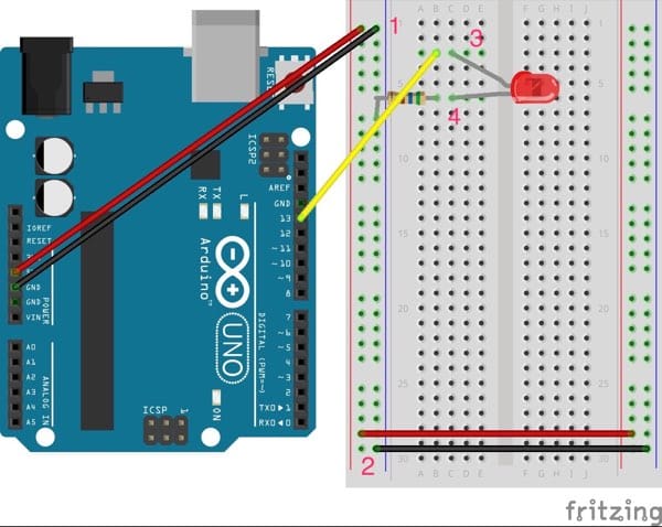
Check it out and see if you can explain what is going on at each location. Reference the previous explanation if you need a refresher. When you’re ready, share your knowledge with one of the program staff!
Why Diagrams?
At this point, you may be wondering why you should understand how to use a diagram when it seems way easier to just follow a list of steps or watch a video.
The benefit is that once you understand how to read diagrams and (eventually) traditional schematics a whole world of projects will open up. There are many project guides and walkthroughs that will provide a diagram or schematic as the first step and expect the reader to understand how to wire the circuit before proceeding with the project.
Combining the ability to work with schematics with an understanding of the basics of input and output and how an Arduino and breadboard work together will give you the skills and confidence to tackle any project that you come across! Even if the project is advanced you can still benefit from trying to read and understand the diagram as this is a great way to develop a foundation.
Going Further
If you’re interested in seeing how schematics differ from the types of diagrams that you’re working within this course, Sparkfun has developed an excellent introduction to traditional circuit schematics: Sparkfun Tutorial: How to Read a Schematic.
Here’s another article from Make Magazine about the importance of reading and understanding diagrams and schematics: Skillset: Reading circuit diagrams.