Basic Circuitry: Breadboarding
Objectives and Overview
This lesson introduces breadboards, a core tool for extending and prototyping your work with electronics. Understanding the basics of using breadboards will level up what you’re able to do while working through this course.
Lesson Objectives
- Explain what a breadboard is and how they’re used for prototyping.
- Recognize the different rails on the breadboard and explain the basic breadboard layout.
Working with Breadboards
The next step in your Arduino experimentation is to start integrating the breadboard. This will greatly expand the number of projects that you can work with. First, let’s examine the breadboard itself.
What is a Breadboard?
Breadboards allow us to create prototypes of circuits and let us expand beyond the basic footprint of the Arduino. They can come in many shapes and sizes but they all have the same basic functionality.

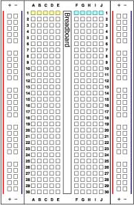
The edge of a breadboard usually has two columns on each side. One marked with a “+” in red and one marked with a “-” in blue. These are called power rails. You would normally use these to connect your power source to your breadboard (more on that later). The holes in each column are connected to each other the entire length of the breadboard but the red and blue columns are NOT connected, they are separate.

The rows on the inner part of the breadboard are one connection with a break in the middle. So hole A1 is connected to hole E1 but NOT to hole F1.
Jumper Wires
Jumpers are wires that bridge connections between two devices. In this project, we are going to use them to connect our Arduino to our breadboard. You can buy specific jumper wires or you can make your own which is what I recommend doing once you have run out of jumper wires.

Wire Color?
The actual color of the wire doesn’t matter when working with Arduino. Wire color can be a useful guide for human beings, but the color is a coating placed on the actual wire. With that said, it’s generally helpful to use red wires for power and black, blue, or green wires for ground connections. However, you’ll need to be flexible since you may find yourself in a situation without red or black wire.