Design to Print Workflow
Objectives and Overview
This lesson provides an overview of the design to print workflow. This is the process that you go through when creating a 3D printed object. This lesson contains a general overview as well as some details about each step. The core goal of this lesson is for the youth to become familiar with the entire process. Often they’ve experienced only one aspect of the entire workflow. This overview will help them recognize and explain each of the steps in the process.
Lesson Objectives
- Understand the process of moving from digital design to a 3D printed object.
- Understand and be able to explain the differences between an STL file and GCode.
- Be able to explain the different steps involved in the outlined design to print workflow.
Design to Print Workflow
Before diving into each of the individual sections, let’s take a look at the process as a whole. This is the path from the design software to the printer software.
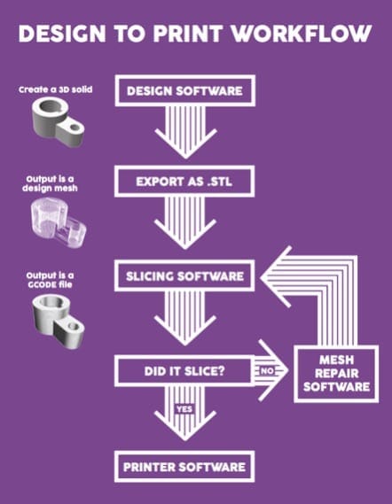
It’s important to note that sketching and physical prototyping would occur not only at the beginning before the design software but also throughout the process. Let’s now take a deeper dive into each section in the workflow, starting with design software.
Design Software
There are many types of design software ranging from beginner-friendly and accessible to complex tools with steep learning curves. The fundamentals of each program can even be completely different! For example, you can have a primitive shape-based tool like Tinkercad as well as tools based on drawing and scanning objects. The core aspect that these tools share is that they can all be used to create files that can ultimately be used in fabrication. This lesson specifically references 3D printing, but there are equally many types of tools for subtractive manufacturing as well.
Regardless of the software used in this phase, the goal is to create a 3D solid:

The most important thing about the design tools that you use is that they export to an STL file, which is often called your design mesh. You can think of this as a wireframe that defines your object’s structure. Think of how a parade float has a wire “skeleton” that defines and provides the structure. The decorations added on top once this structure has been defined.
This course uses Tinkercad as the main design tool. Tinkercad has a lot of depth to it and you’ll be exploring some more intermediate concepts that will prepare you for using a more powerful tool such as Fusion 360.
Exporting STL Files
Once you’re ready to have a printable version of your design, you export the STL file from the design software. STL stands for Stereolithography, and the origins of this file format are in the 1980s. STLs describe only the surface of a 3D object and doesn’t typically include any information about an object’s texture or color.
This is a very common question from new learners and it’s important to clarify this point. The STL file produced by the design software only includes structural information. It’s very helpful to continually emphasize the wireframe analogy — the information in an STL defines the structure of an object in the same way that a wireframe defines the structure of physical construction.
Slicing Software
After the STL is created, the next step in the workflow is to slice the object. Remember, the core of additive manufacturing is the concept of layers. The additive manufacturing video examples in previous lessons demonstrated how layers of material are added one at a time until an object is completely fabricated.
Slicing software is where your design is transformed into a series of layers. This process is called slicing since you’re taking the structural information of your object that is included in the STL and then slicing it into individual layers that machines can understand.

The slicing software takes the structural information present in the STL file and then outputs the machine-readable GCode. GCode is the file format that the 3D printers need since it contains information about the coordinates and layer height. Again, remember that additive manufacturing builds by adding materials layer by layer and these layers are generated from the design mesh (the STL file). The GCode file is an array of individual 2D layers that the printer then receives as commands such as the X and Y coordinates as well as the layer height.
This is a crucial point to understand and is a core objective for this lesson. If you were to try to upload an STL file directly to a 3D printer the printer wouldn’t recognize the file.
Slicer software is similar in that the core functionality is to output sliced layers into a machine-readable format. However, different slicing software has different settings that you can adjust to. There is lots of free slicing software out there, but some printers even come with their own specific slicers. In this course, you’ll be exploring FlashForge, the slicing tool used for the FlashForge Finder printers.
Even though the slicing tools may look different, understanding the basic functionality builds a solid foundation that can transfer from tool to tool.
Slicing Examples
Let’s take a look at this process by looking at a visual example. This is a scan of Adam, one of our DHF staff members. This first image is the STL, which is the design mesh:

We created a visual aid to help with understanding the slicing process. To do this, we took the sliced output and then laser cut individual cardboard layers to show how the original object was sliced. Looking at this next image you can see the layers that are then stacked, one at a time, on top of each other to form the physical shape.
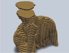
Once all the layers are stacked, the output resembles the original design mesh’s shape. This is an effective way to visualize the slices.

Each of these layers would be output from the 3D printer. Thinking back to the video examples, these layers are what is laid down by the printer. After each layer is complete, the printer then moves up to the next layer.
Handling Slicing Issues
Sometimes there are slicing issues. Slicer software often provides insight into the occurring errors. These are often a result of technical issues that can be solved in the design phase. Solving some of the specific slicing issues is out of the scope of this course. The core takeaway is that if slicing issues occur, your first step is to revisit your design and make sure that it is printable.
Often, issues such as floating objects or designs being beneath the print bed cause slicing errors. At this point in your learning, it’s helpful to build solid habits of evaluating designs when there are issues.\
Printer Software
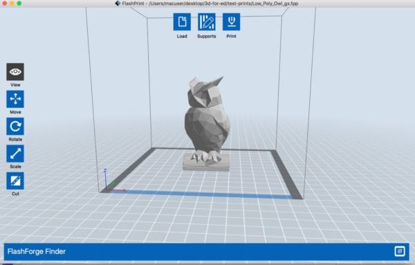
The last step in the workflow is printing software. This is the software that actually controls the printer itself by sending machine code commands to it. Most often, you’ll load the GCode file into your printer software and the software then sends each line of GCode to the printer. The GCode contains information that tells the printer what to do. In this course, FlashPrint acts as both the slicing software and the printer software. Here’s an example of an object loaded into FlashPrint.
As you move through this course, pay attention to each of these steps! It’s a lot to take in at first, but it’s a natural workflow and one that you’ll use throughout your additive manufacturing development.